FAQ – Frequently Asked Questions (10 Q&A)
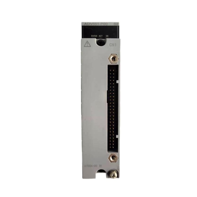
Q1: How many output channels does the ADV551‑P00 provide?
A1: It provides 32 discrete digital output channels in one module.
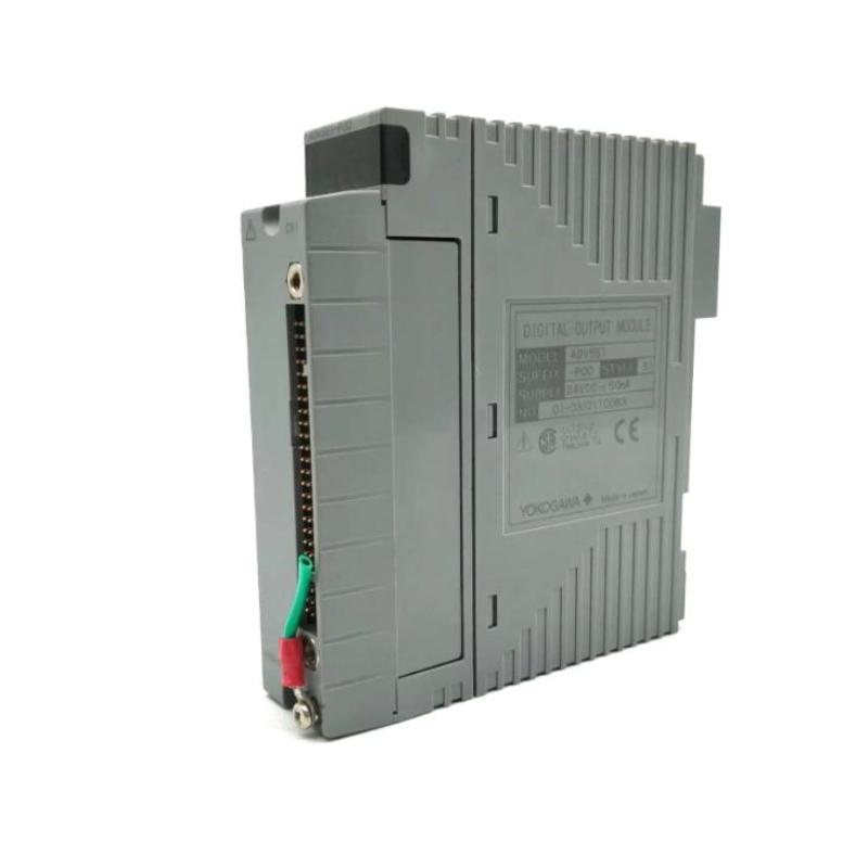
Q2: What voltage does this module operate on?
A2: The module uses a nominal 24 V DC applied voltage, typically in a range of 20.4 to 26.4 V DC.
Q3: What is the maximum load current per channel?
A3: Each channel can handle up to approximately 100 mA when operating near the upper supply voltage (~26.4 V).
Q4: How fast does the module respond when an output is activated?
A4: For status ON/OFF outputs the response time is ≤ 3 ms; when using mixed status and pulse‑width outputs the response may be ≤ 10 ms.
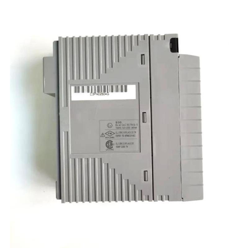
Q5: What are the physical dimensions and weight of the module?
A5: Dimensions are approximately 107.5 mm wide × 130 mm high × 32.8 mm deep. Weight is about 0.20 kg (200 grams).
Q6: What type of output format does the module use?
A6: It uses current‑sink digital outputs suited for field devices compatible with 24 V DC control.
Q7: Can the module support advanced output functions such as pulse width or time‑proportioned outputs?
A7: The base “P00” version is focused on ON/OFF status outputs. However, the ADV551 series overall includes variants (e.g., P50) that support pulse width and time‑proportioning output functions.
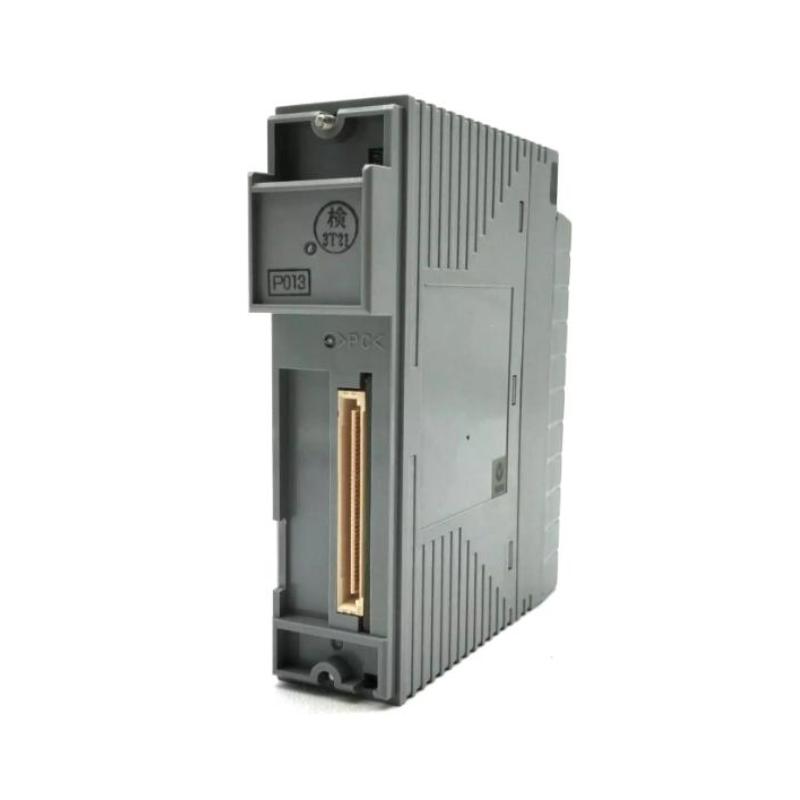
Q8: Is this module compatible with the Yokogawa I/O platform and backplane?
A8: Yes — the module is part of the ADV551 series designed for Yokogawa I/O base frames, backplanes and cable systems, enabling integration with control systems and ease of replacement/spare parts.
Q9: What operating environment conditions does it support?
A9: Typical ambient operating conditions are from approximately −20 °C to +60 °C, and it is built to function in industrial automation environments with appropriate ventilation and wiring shielding.
Q10: How should I replace or maintain this module in the system?
A10: To replace: power down the I/O rack or isolate the backplane; remove the module; install the replacement into the same slot; reconnect any field wiring or terminal blocks; restore power; and perform channel tests to verify correct output functioning. Regular inspection of wiring, terminals and module seating is also advised.
Related Products
Copyright @ 2026 Automations
XML|Links:
No:77501