FAQ – Frequently Asked Questions (10 Q&A)
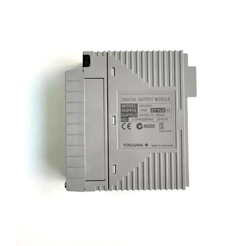
Q1: How many output channels does the ADV551‑P00/D5A00D provide?
A1: It provides 32 discrete digital output channels in a single module.
Q2: What voltage does each output channel operate at?
A2: The outputs operate at a nominal 24 V DC applied voltage.
Q3: What is the maximum load current per channel?
A3: Each channel is rated for approximately 100 mA when operating near the upper voltage (~26.4 V DC).
Q4: What is the module’s response time?
A4: For normal ON/OFF status outputs the response time is ≤ 3 ms; if pulse‐width or time‐proportioning modes are used (in variant modules), the response may be ≤ 10 ms.
Q5: What are the physical dimensions and weight of the module?
A5: Dimensions are approximately 107.5 mm (width) × 130 mm (height) × 32.8 mm (depth); weight is about 0.20 kg.
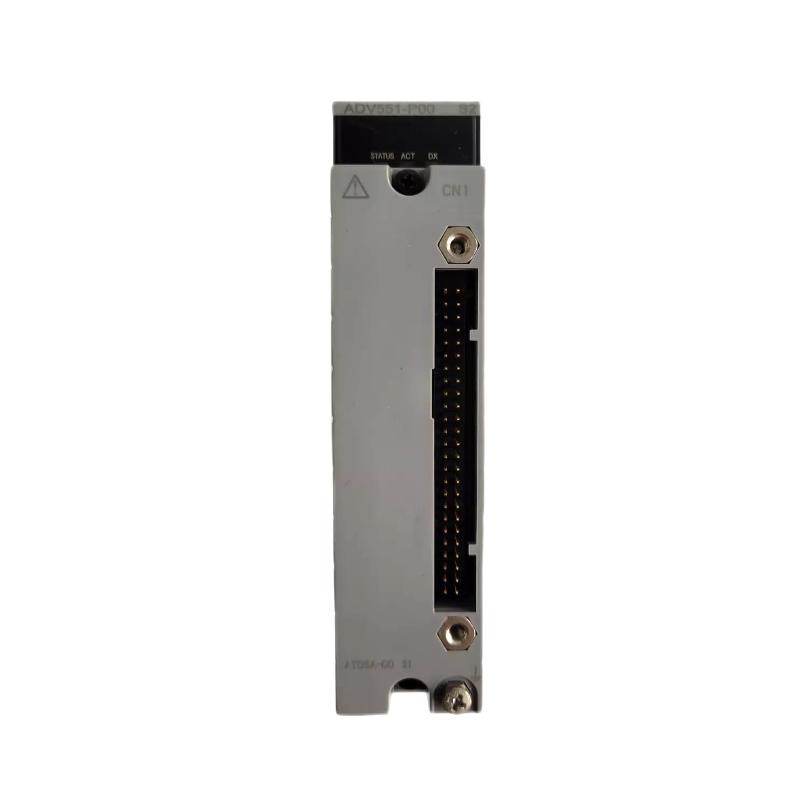
Q6: What output format is used (sink or source)?
A6: The module uses current‑sink type digital outputs, compatible with standard 24 V DC field devices wired for sinking.
Q7: Does the suffix “/D5A00D” indicate any special feature?
A7: Yes, the “/D5A00” portion denotes that a specific interface adapter (e.g., KS cable interface) is included; the “D” suffix may indicate a variant version of the option kit. In effect, it simplifies field wiring by including tailored cable/terminal accessories.
Q8: Is the module compatible with the Yokogawa modular I/O platform?
A8: Yes – the module is part of the ADV551 series and integrates into Yokogawa base frames/backplanes designed for that series, enabling plug‑in installation, spare part consistency and system compatibility.
Q9: What ambient environment conditions is the module designed for?
A9: The module is designed for typical industrial automation environments—about ‑20 °C to +60 °C ambient temperature (typical for the base version), with suitable ventilation and field wiring practices.
Q10: How should I maintain or replace this module in a system?
A10: To maintain or replace: power down or isolate the I/O rack/backplane, remove the module from its slot, insert the replacement module, reconnect any required wiring or terminal blocks, power up the system and verify that all output channels are functioning. Regular checks of wiring connections, terminal blocks and ventilation are recommended.
Related Products
Copyright @ 2026 Automations
XML|Links:
No:77501