❓ Frequently Asked Questions (10 QA)
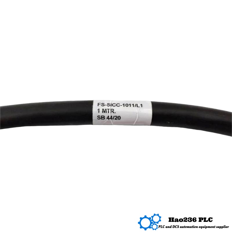
Q1: What does “L15” mean in the model FS‑SICC‑1011/L15?
A1: The “L15” designation normally indicates the length or immersion portion of the sensor (150 mm) or a specific lead length or mounting variant configured for that unit.
Q2: Can the sensor detect through non‑metallic walls or containers?
A2: Yes: in non‑metallic (e.g. plastic, glass) containers, the capacitive field can sense fluid level through the wall (non‑contact) if wall thickness and dielectric constants allow.
Q3: Does it support both analog and switch outputs?
A3: Some variants are selectable or dual output; typically you configure either a continuous analog signal (e.g. 4–20 mA or 0–5 V) or a switch output depending on the particular model.
Q4: How often must it be calibrated?
A4: Under normal stable conditions it requires little calibration — drift is minimal (< 0.1 % FS per year). Occasional verification is recommended in critical applications.
Q5: What fluids are compatible?
A5: It is compatible with many aqueous, chemical, and organic liquids—provided those fluids do not degrade wetted materials (PEEK, PTFE, etc.). Avoid strong acids, caustics, or solvents incompatible with the sensor materials.
Q6: Can it operate in high temperatures?
A6: Yes. The operating range is –20 °C to +85 °C. Above or below this range damage or measurement error may occur.
Q7: How fast does it respond to level changes?
A7: The response time is typically <100 ms, which is sufficient for many process control loops.
Q8: What mounting orientations are allowed?
A8: It can be mounted vertically or horizontally. For best performance, immersion orientation aligned with fluid level changes is recommended.
Q9: Is the sensor susceptible to drift or fouling?
A9: Over time, buildup of deposits can slightly shift readings. Periodic cleaning (compatible solvents) and periodic calibration checks mitigate drift.
Q10: What kind of signal conditioning is needed?
A10: For analog outputs (4–20 mA or 0–5 V), you may use signal isolation, filtering, or calibration circuits. For switch outputs, pull‑up resistors or buffer circuits might be required depending on your control system.
Related Products
Copyright @ 2026 Automations
XML|Links:
No:77501