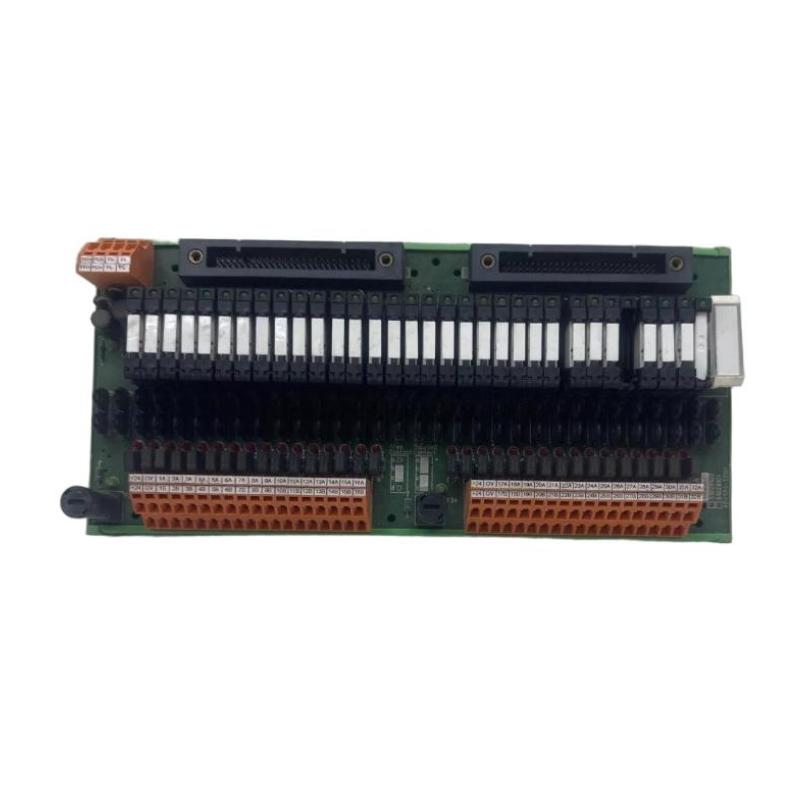
FAQ (10 Common Questions – QA Format)
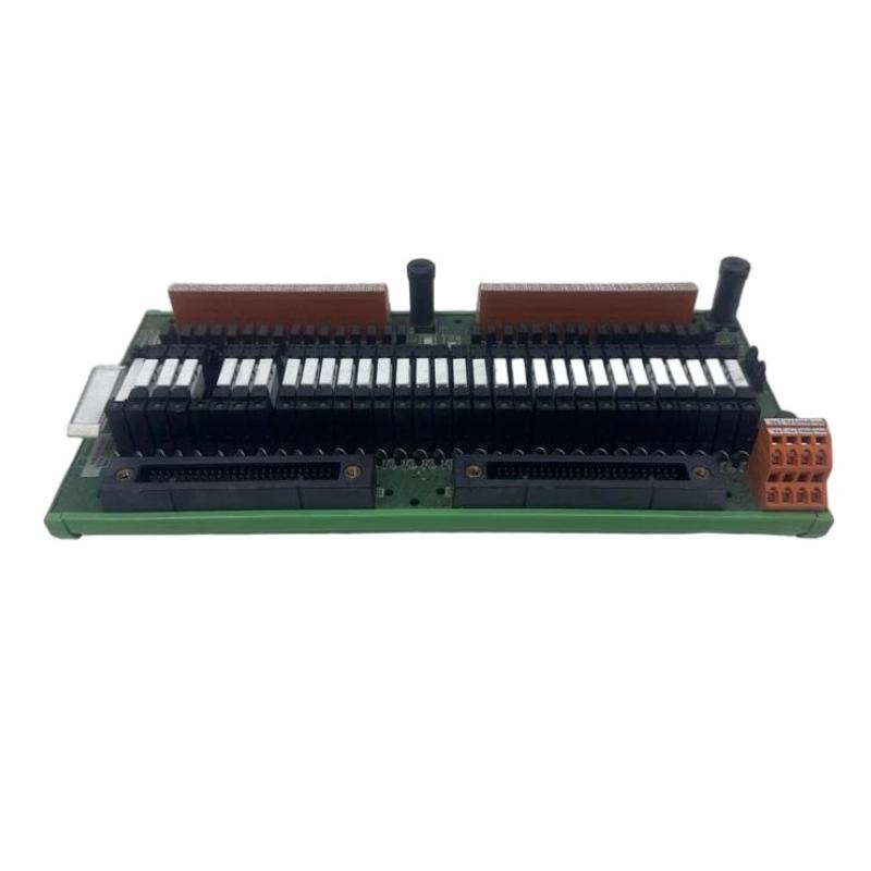
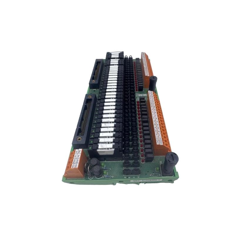
Q1: How many output channels does the ADV551‑D032 have?
A1: It provides 32 discrete digital output channels in one module.
Q2: What is the nominal operating voltage for the module?
A2: The module is designed for 24 V DC nominal output voltage.
Q3: What is the maximum current that each channel can drive?
A3: Each output channel can handle up to approximately 100 mA when operated at around 26.4 V DC.
Q4: What is the switching speed of the outputs?
A4: For status (ON/OFF) outputs the response time is typically ≤ 3 ms; if pulse width or mixed modes are used, the response may be up to ~10 ms.
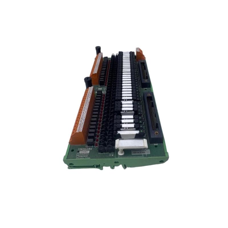
Q5: What are the physical dimensions and weight of the module?
A5: Approximately 107.5 mm wide × 130 mm high × 32.8 mm deep, and the weight is around 0.20 kg.
Q6: Is the module compatible with the Yokogawa I/O system platform?
A6: Yes. The module is part of the ADV551 series and integrates with Yokogawa base frames, backplanes and the same rack system used throughout the brand’s digital I/O family.
Q7: Can the module support advanced functions such as pulse‑width or time‑proportioning outputs?
A7: Yes—depending on the exact variant (suffix/option code) of the ADV551 series, the module may support one‑shot pulse width outputs (8 ms to 7200 s) and time‑proportioning output control.
Q8: What types of field devices can this module drive?
A8: It can drive any discrete output device compatible with 24 V DC current sink type control—such as solenoid valves, indicator lamps, motor contactors, relays, or other field actuators requiring discrete control signals.
Q9: What is the typical environment and conditions for safe operation?
A9: The module is designed to operate in industrial automation environments with ambient temperatures around –20 °C to +60 °C (depending on variant) and moderate humidity, and it features isolation and robustness to handle electrical noise and wiring runs.
Q10: What is involved when replacing or maintaining this module in a control rack?
A10: Power down the I/O rack or isolate the backplane, remove or unplug the existing module, install the new module into the slot, reconnect wiring or terminal blocks, restore power, and perform channel verification tests. Regular checks of cable connections, terminal tightness and module ventilation are recommended.
Related Products
Copyright @ 2026 Automations
XML|Links:
No:77501