FAQ – Frequently Asked Questions (QA Format)
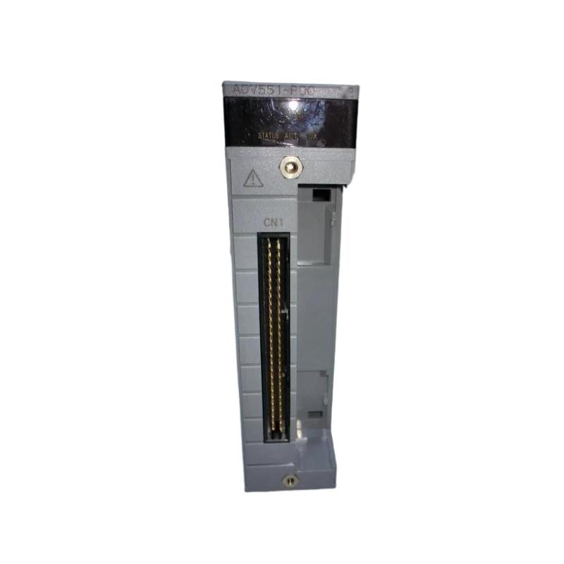
Q1: How many output channels does the ADV551‑P00/D5S00 provide?
A1: It provides 32 discrete digital output channels in a single module.
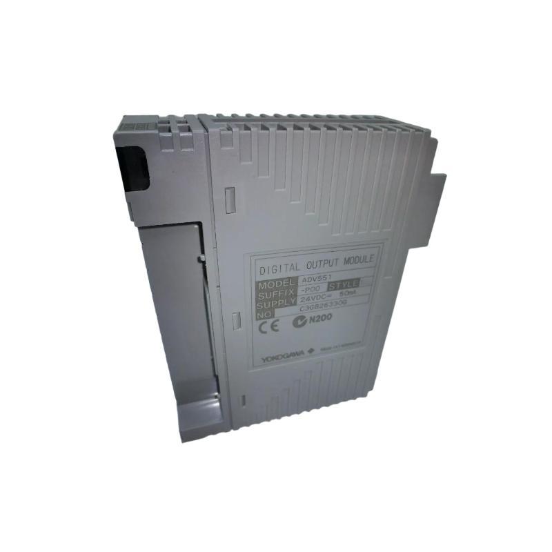
Q2: What is the rated applied voltage for the module’s outputs?
A2: The module is designed around a 24 V DC nominal applied voltage.
Q3: What is the maximum current that each output channel can drive?
A3: Each channel can drive approximately 100 mA at the upper supply voltage (~26.4 V) under rated conditions.
Q4: What is the typical response time when switching an output?
A4: For standard OK/OFF status output the response time is ≤ 3 ms; when using pulse width or mixed status/pulse modes it may be up to ≤ 10 ms.
Q5: What are the physical dimensions and weight of the module?
A5: The dimensions are approximately 107.5 mm wide × 130 mm high × 32.8 mm deep, and the weight is about 0.20 kg.
Q6: What type of output format does this module implement (sink or source)?
A6: This module uses current‑sink digital output format, suitable for typical 24 V DC field devices.
Q7: Does this module support advanced output features such as pulse width or time‑proportioning outputs?
A7: The P00/D5S00 variant supports ON/OFF status outputs; although the series includes variants (e.g., P50) that support pulse width and time‑proportioning functions.
Q8: Is the module compatible with Yokogawa’s modular I/O rack and base frames?
A8: Yes—the ADV551‑P00/D5S00 is part of the ADV551 series, designed to integrate with the standard base frame/backplane system of Yokogawa I/O architecture, making installation, replacement and maintenance more straightforward.
Q9: What ambient temperature conditions can it operate under?
A9: It is rated for approximate operation from ‑20 °C to +60 °C (typical), assuming proper cabinet ventilation and installation practices for industrial environments.
Q10: How should one replace or maintain this module in a control cabinet?
A10: To replace or maintain: power down or isolate the I/O rack/backplane, remove the module, insert the replacement in the same slot, reconnect any required field wiring terminals, restore power, and verify that all output channels function correctly. Regular wiring and terminal integrity checks are also advisable.
Related Products
Copyright @ 2026 Automations
XML|Links:
No:77501