FAQ – Frequently Asked Questions (QA Format)
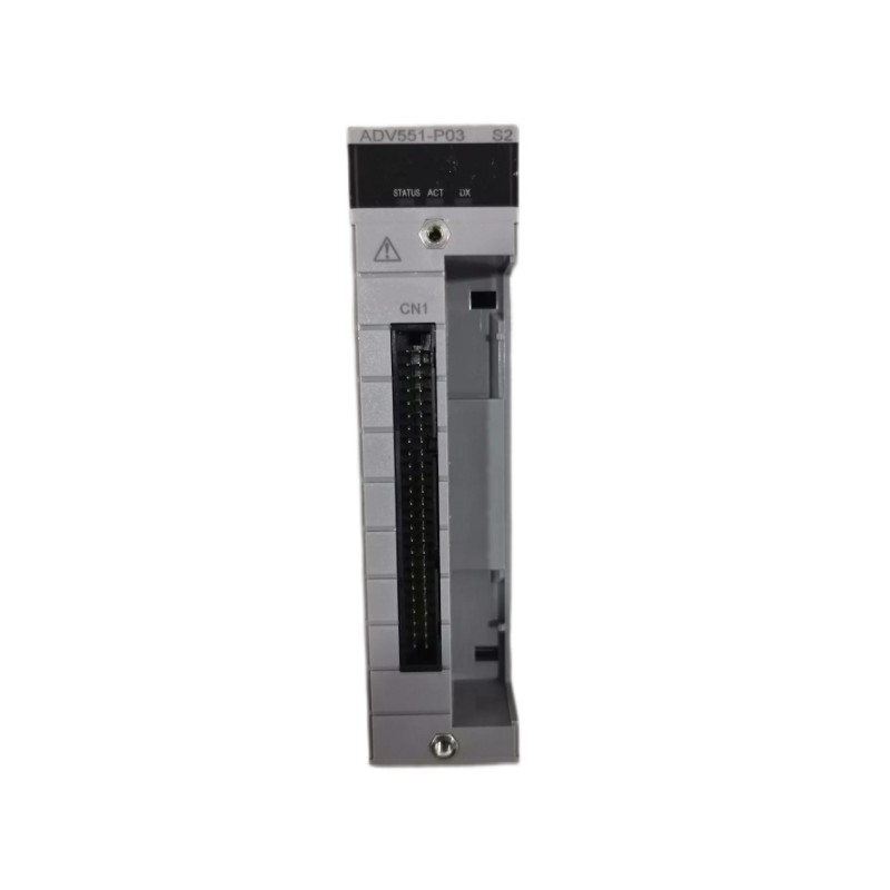
Q1: How many output channels does the ADV551‑P03/D5A00 provide?
A1: It provides 32 discrete digital output channels in one module.
Q2: What is the nominal applied voltage for this module?
A2: The module is designed for a nominal applied voltage of 24 V DC for its output devices.
Q3: What maximum current can each channel handle?
A3: Each channel is rated for up to approximately 100 mA when operated at around 26.4 V DC.
Q4: What is the response time when an output is switched on or off?
A4: For status outputs the response time is ≤ 3 ms; if operating in mixed status/pulse modes, the response time may be up to ≤ 10 ms.
Q5: What are the physical dimensions and weight of the module?
A5: The module measures approximately 107.5 mm wide × 130 mm high × 32.8 mm deep, and weighs about 0.20 kg.
Q6: What output format is used—current sink or source?
A6: The output format is current‑sink type digital outputs, which is compatible with typical 24 V DC field devices.
Q7: Does the module support advanced output functions like pulse width or time‑proportioning?
A7: While the P03/D5A00 variant focuses on ON/OFF status outputs, the series includes variants (such as P50) that support pulse width or time‑proportioning output functions.
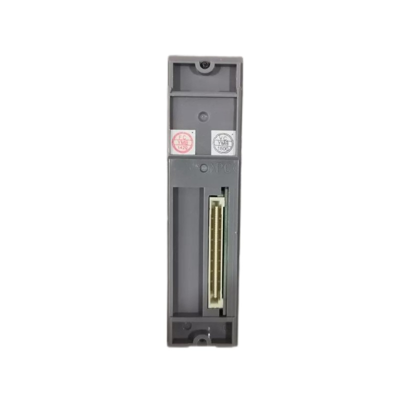
Q8: What field‑wiring interface does this specific model use?
A8: The “/D5A00” option indicates it uses a KS Cable Interface Adapter for 32‑channel digital output—enabling a clean cable‑based connection rather than only terminal blocks.
Q9: Is this module compatible with the brand’s modular I/O base frames and backplanes?
A9: Yes—being part of the ADV551 series, it integrates with the standard I/O base frames, backplanes and field‑wiring setups of the brand’s automation platform, facilitating system integration and spare‑parts management.
Q10: What is involved in installing or replacing this module in a system rack?
A10: To install/replace: power down or isolate the I/O rack/backplane, remove any existing module, insert the new module into the same slot, connect the KS‑cable or field wiring as required, power up, and verify each output channel’s function. Regular checks of wiring connections, module seating and ventilation are advisable.
Related Products
Copyright @ 2026 Automations
XML|Links:
No:77501