FAQs (10 Questions & Answers)
Here are ten real‑world style FAQ items about IS200EISBH1A, avoiding overly “AI‑style” phrasing, focusing on field usefulness.
QA1
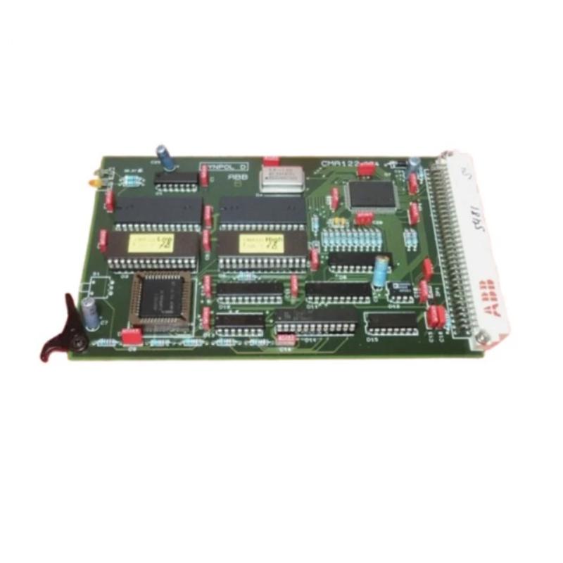
Q: Where is the IS200EISBH1A board located inside the rack?
A: It is mounted in the control rack under the DSPX controller. It occupies a single slot, 3U height.
QA2
Q: What signals does the EISB board receive and transmit?
A: It accepts fiber‑optic feedback signals from generator field modules, optional exciter feedback; it also communicates ground detection input/output; sends these to controllers via the backplane; additionally supports RS‑232C for tool/keypad ports.
QA3
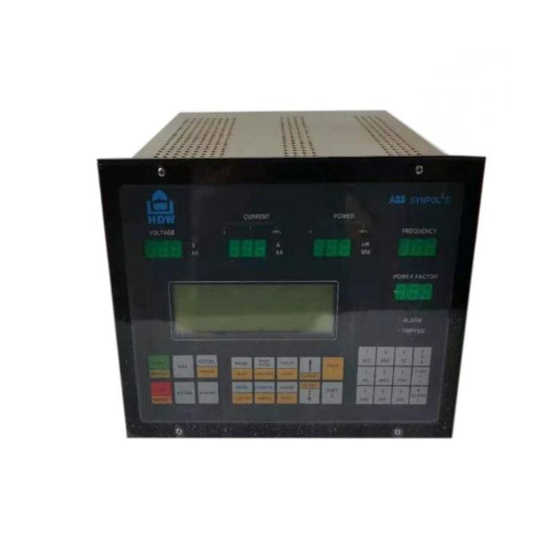
Q: How many indicators are there and what do they show?
A: There are six front‑panel indicators: Generator Field Voltage, Generator Field Current, Exciter Voltage, Exciter Current, Ground Detect Input, and Ground Detect Output.
QA4
Q: Does the EISB board manage gate‑pulse generation or is that done elsewhere?
A: Gate pulses are handled by other boards (such as ESEL / EGPA) downstream. The EISB mainly handles feedback / communication of field current / voltage and ground detection, not direct gate pulse drive.
QA5
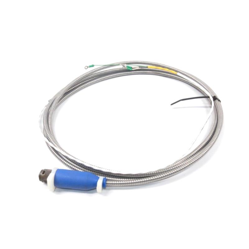
Q: What happens if the fiber‑optic feedback link fails?
A: The system will likely detect loss of feedback, trigger alarms; controllers may default to safe or fallback mode. The integrity of field feedback is critical.
QA6
Q: Is the EISB board required in redundant setups?
A: Yes. In redundant systems with multiple controllers (C, M1, M2), the EISB is essential to allow communication / feedback sharing; without it, redundancy loses much of its benefit.
QA7
Q: What voltage supply does this board need?
A: It operates off 24 V DC for its logic and internal components.
QA8
Q: Can the board accept optional exciter feedback signals?
A: Yes—reads from generator field voltage/current by default, and optionally exciter feedback if EDCF boards are used for that purpose.
QA9
Q: What are the environmental or temperature limits?
A: The published sources do not always give full ranges; however, as with similar EX2100 modules, it is expected to operate in industrial/turbine ambient conditions—probably from about ‑30°C up to +65°C or greater.
QA10
Q: How easy is it to replace the board in field service?
A: Replacement is fairly direct: de‑energize system; open control rack; remove screws / captive hardware; pull module (single slot) from rack; reinsert new board; reconnect fiber‑optic connectors and tool/keypad ports; verify indicators once powered.
Related Products
Copyright @ 2026 Automations
XML|Links:
No:77501